DIY: Control a AC light using ESP32 dev board
Table of Contents
Control a led light using ESP32
Recently I just bought a new ESP32 dev board to tinker with its wireless capabilities. After setting it up in the Arduino IDE and running into some basics I tried building something that is actually useful.
How about controlling a device remotely, maybe switching off lights in my room without getting off my bed. That sounds cool right.
After a liitle bit of googling, I found this pretty easy to setup. All it required was a relay module and some connection wires. I didn’t have the module, so I decided to build one. Most of the premade modules have unneccessary components buit into them, so you could get rid of them by making one. Btw the custom one is much cheaper too.
Components
-
ESP32
-
5v relay
-
1k resistor
-
1N4007 diode
-
2N2222 or 2N3904 transistor
1. The basics
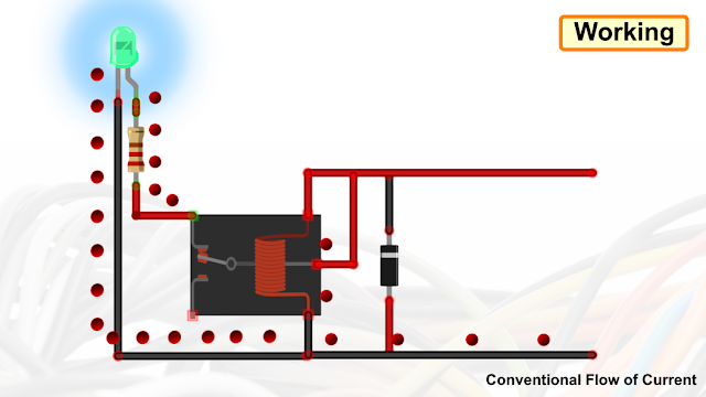
The esp32 is the brain that decides how a relay is driven. We will use its wifi capability to act it as a Web Server. The server will contain a switch that will toggle the appropriate digital pin on the board. A transistor is connected to drive the relay, since the output current of esp32 is so weak to drive it directly.
Once the relay is activated, the circuit of the led is completed and LED turns on.

Word of caution: This circuit uses a relay to turn on the mains voltage. Improper connection may lead to short circuits. So proceed with care.
2. Making the relay module
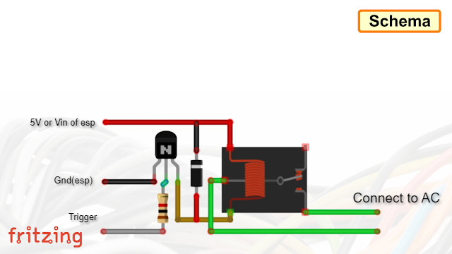
Wire the circuit according to the below diagram.

The relay used here is 5V since it can be driven directly from input usb of esp32. Any other higher voltage specification will need a seperate power source. But I connected it to the same input of esp32.
Using seperate power source is so much safer. This method can be highly effective if an optional octocoupler is added. This will provide complete isolation to the digital circuit even if the transistor fails.
Here is how mine ended up like.

Make sure you test the module before connecting it to the mains voltage.
3. Uploading the code
Upload the code. Here is the github repo.
Identify if you need the relay to work in normally-open(NO) or normally-closed(NC) configuration. You can find the help in references
Change the relay config or the output pin as required (Here, D26 pin of esp is given as output). Give the SSID and Password of your network since esp32 requires those credentials to connect to the network once it is booted, change it in the code.
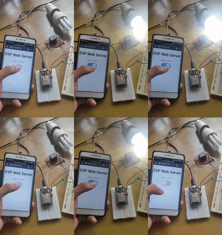
Once the code is uploaded. Boot the esp32, and the ip address (default:192.168.43.193) that you need to connect will be shown in the serial monitor. On successful connection you will be greeted with this screen.

Now power on the esp and try if you can switch the relay. If all goes well, you will hear the sound of relay making the connection.
Adding it all up
Combine the esp32 with the relay module. Connect an LED to output of relay.
Make sure the current rating of the led is far below the current rating of the relay. And don’t connect high current appliances.
Before plugging it in, ensure that the connections are proper by using a multimeter.
Now connect the mains and power up the esp32.

References
- [https://arduinogetstarted.com/tutorials/arduino-relay]
- [https://forum.arduino.cc/t/12v-relays-or-5v-relays/628634/8]
- [https://randomnerdtutorials.com/esp32-esp8266-relay-web-server/]
- [https://howtomechatronics.com/tutorials/arduino/control-high-voltage-devices-arduino-relay-tutorial/]
- [https://www.circuitbasics.com/setting-up-a-5v-relay-on-the-arduino/]